Assembly Guide
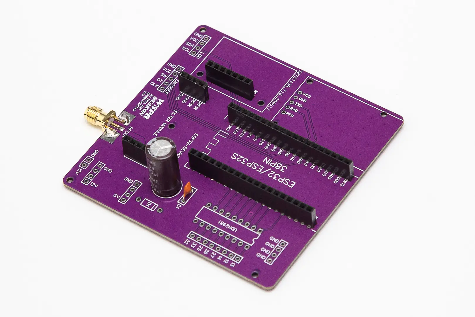
This guide provides step-by-step instructions for assembling components on the main PCB of your WSPR Beakon. Follow these instructions carefully to ensure proper assembly and operation.
Main PCB Component Assembly

When assembling the various components on the main board, it is recommended to follow this order:
1. Initial Verification
- Verify that the pin silkscreen of the different modules matches the silkscreen of the main board, as there may be different versions of modules with different pinouts
2. Filter Socket Installation
- Solder the two 4-pin female sockets for the filters, pressing them against the board during soldering so they are properly seated and form 90 degrees with respect to the board
3. ESP32 Socket Installation
- Solder the female pin sockets for the ESP32, taking care that they are properly seated and therefore form 90 degrees with respect to the board
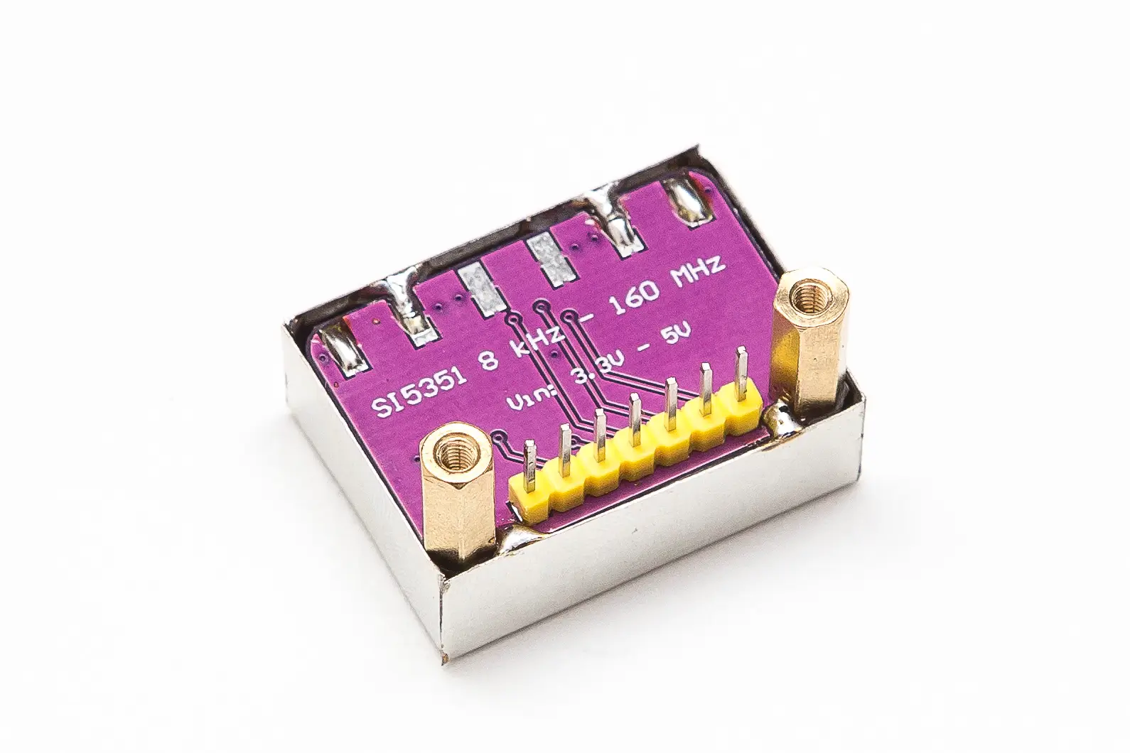
4. Si5351 RF Module Socket Installation
- Solder the female pin sockets for the RF module (Si5351), taking care that they are properly seated and therefore form 90 degrees with respect to the board
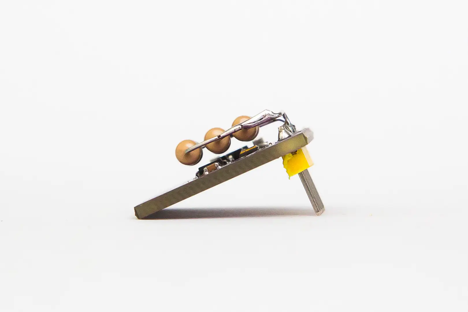
5. Si5351 Module Pin Installation
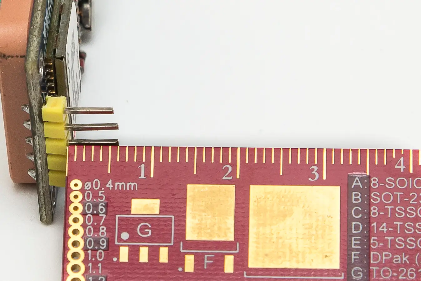
- Solder the seven-pin male strip on the Si5351 module. These pins are inserted from the bottom of the board (solder on top) and the long part of the pins should be visible. Take care that they form a 90-degree angle with the board
6. Frequency Stability Enhancement
Once the pins are soldered on the Si5351 module, solder 3 resistors of 100 ohms and 1 watt, in parallel, on the pins marked as "VIN" and "GND". These resistors will be 1 or 2 millimeters above the board components to act as a "heater" for them and thus minimize frequency drift of the module.


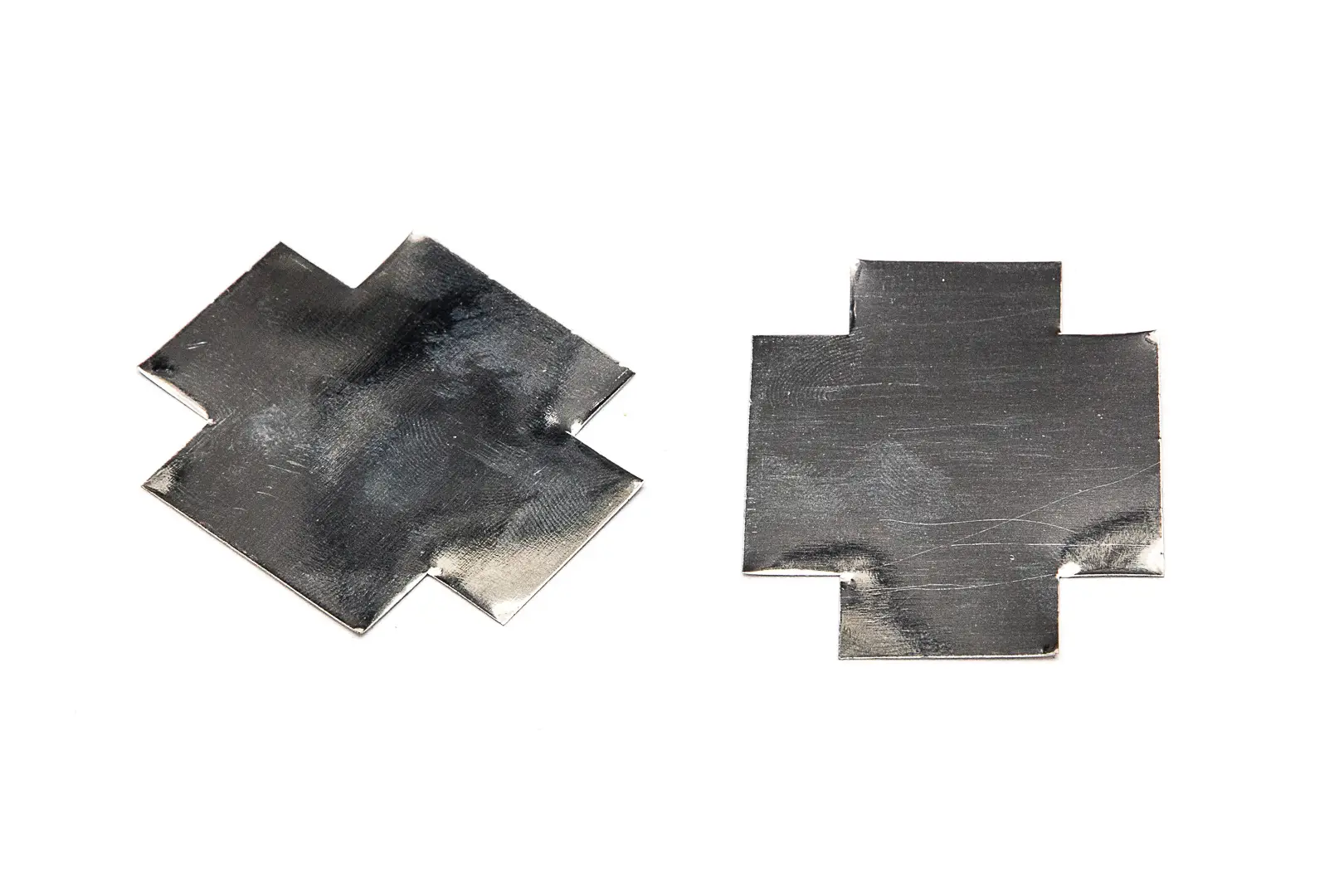
Optional Temperature Stabilization Enclosure
If you want to further improve frequency drift, you can prepare a small box for the Si5351 module that encloses it and the resistors to maintain internal heat. A tinned metal sheet can be used to make this box (the sheet from condensed milk cans from a well-known food brand is optimal due to its ease of being soldered with tin). In this case, it is necessary to mount the standoffs on the module before soldering the housing on the bottom of the board at four points, and generally two resistors are usually sufficient instead of the three planned if the module is not "enclosed".

Frequency Drift Verification
The final drift of the module can be checked (preferably on 10 meters as it is the highest band and therefore most critical), after having it turned on for 10 minutes, by receiving it ourselves, or also on the "wsprnet.org" website, "Database" section, searching for our reports sent by other stations (in "Call" we will put our callsign). If the "Drift" section shows values of -1, 0, or 1, everything is going reasonably well.
- Positive values (2, 3, or 4): Indicates we are overheating the module - remove one resistor or separate them a bit from the board components
- Negative values (-4, -3, or -2): Indicates the module requires more heat; add a third resistor (if there are only two) or move them closer together
- Deviations of ±5 or more: Will be undecodable frames and will appear clearly tilted in the "Waterfall" of programs like WSJT-X
7. Header Pin Installation
- Solder the male pin strips (short side resting on the board) corresponding to "LCD" (4 pins) and "Encoder" (5 pins)
8. Capacitor Installation
- Solder capacitors C1 (100 nF) and C2 (1000 μF), respecting the polarity of the latter
9. RF Output Connector
- Solder the output SMA connector (RF OUT) if you plan to use it in the position provided on the board; otherwise, you must reroute the RF using a coaxial cable to the location where the RF output connector being used is installed
10. Module Installation
- Insert the ESP32 module into its respective socket (its USB connector will face outward from the board; verify that the ESP32 and main board pin nomenclature match)
- Insert the Si5351 module (secure it with M2.5 x 11mm standoffs to the main board)
- Insert the filter corresponding to the band where the WSPR transmitter will be used (orient it correctly on the board; the "IN" side should face the Si5351)
11. Display and Encoder Wiring
- Wire the LCD and encoder to their respective sockets with female-to-female "Dupont" cables, respecting the pin nomenclature shown on the silkscreen of the corresponding boards
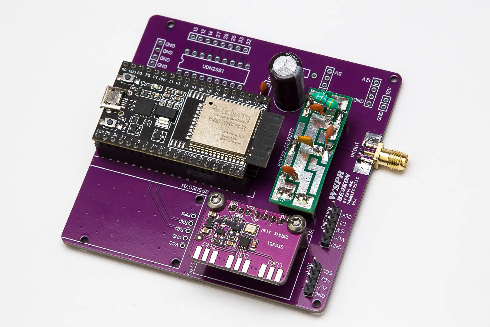
Assembly Progress Check
The board should now look approximately like this:
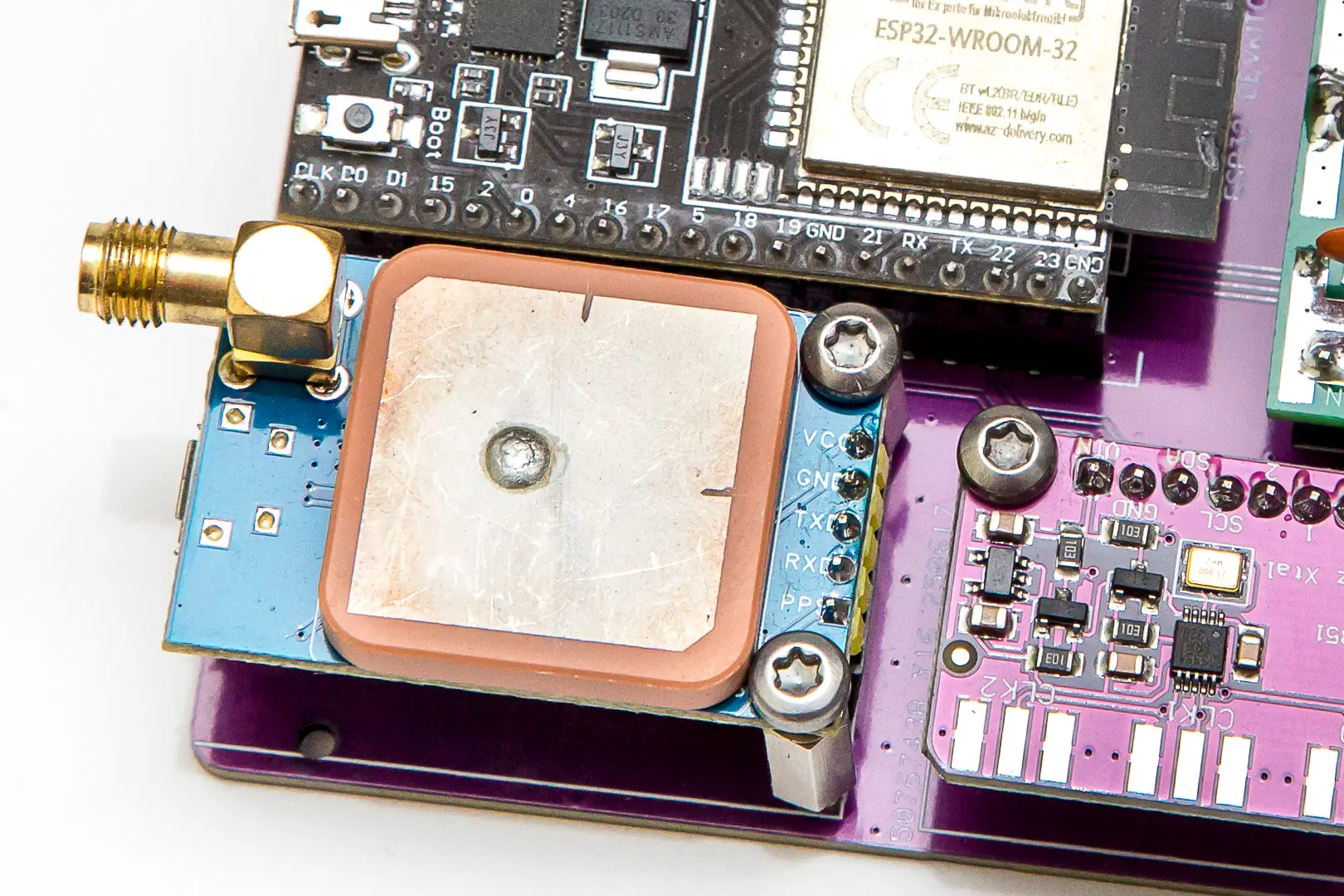
Enhancement 1: GPS Module Installation
If you want to upgrade the board with "Enhancement 1" (GPS), follow these steps:
12. GPS Socket Installation
- Solder a 5-pin female socket in the corresponding position on the main board, taking care that it is properly seated and therefore forms 90 degrees with respect to the board
13. GPS Module Pin Preparation
The GPS board comes with pins protruding parallel to the board, and they must be bent so they protrude at 90 degrees. This is a simple operation but must be done with some care to avoid breaking any pin.
DO THIS PIN BY PIN, NOT ALL AT ONCE. Grip each pin as close as possible to the plastic part with fine-nose pliers and gently bend it to be 90 degrees to the board. Repeat with all five pins. Once done, check that they are all reasonably aligned and adjust if necessary.
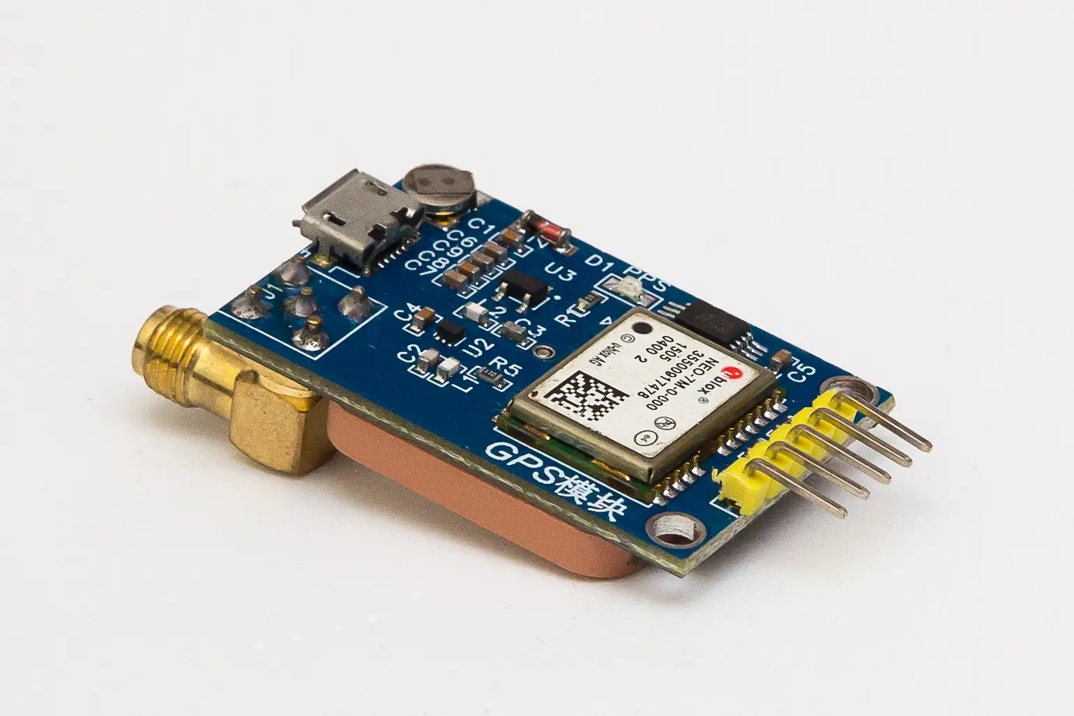
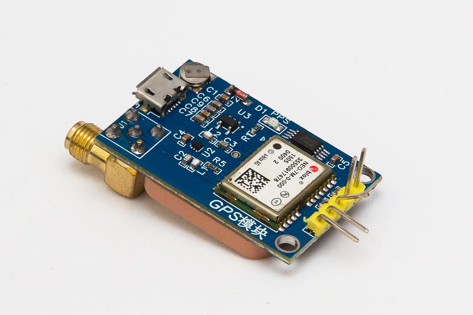
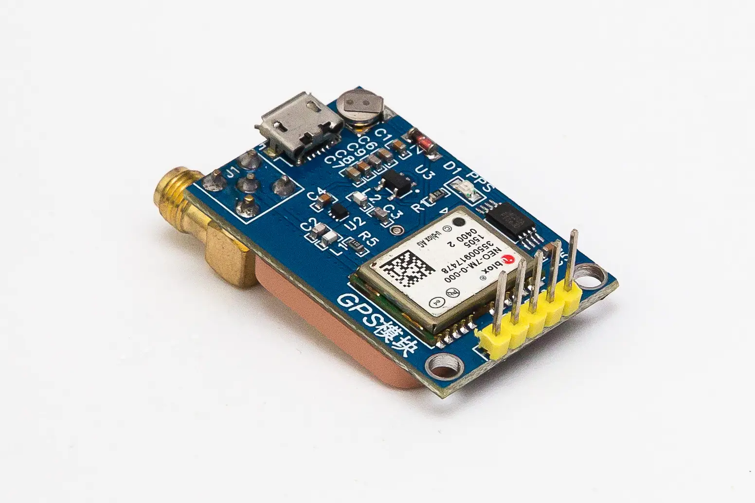
14. GPS Pin Trimming
The pins, once straightened, are longer than necessary and therefore do not seat fully in the female socket. Cut them to approximately 6 millimeters, measuring from the plastic piece.
15. GPS Module Installation
- Insert the GPS module into its socket and secure it with M2.5 x 11mm standoffs to the main board
This area of the board should look approximately like this:
Enhancement 2: 12V External Power Supply
If you want to upgrade the board with "Enhancement 2" (12V external power), follow these steps:
16. Power Input Header
- Solder the 2-pin male strip (short side resting on the board) in the position marked as "GND" and "12V"
17. DC-DC Converter Sockets
- Solder the two 4-pin female sockets in the corresponding position for the DC-DC converter, taking care that they are properly seated and form 90 degrees with respect to the board
18. Corner Pin Installation
- Insert only 4 male pins (from the long side) in the 4 corners of the rectangle formed by both female sockets (positions marked on the board as GND, 12V, GND, 5V). The two center pins of each 4-pin female socket are not used


19. DC-DC Converter Installation
- Place the DC-DC converter board on the four male pins (careful: check that the "IN" and "OUT" silkscreen of the converter board faces down toward the main board and matches the "12V" (for "IN") and "5V" (for "OUT") silkscreen of the main board)
- Ensure it seats properly and solder the 4 male pins
20. Diode Installation
- Solder diode D1 (1N5819) respecting the anode-cathode position as shown on the board silkscreen
This area of the board should look approximately like this:

Enhancement 3: External Relay Control
If you want to upgrade the board with "Enhancement 3" (external relay control), follow these steps:
For this part to work, it is necessary to have previously implemented "Enhancement 2"
21. UDN2981 IC Socket
- Solder the 18-pin socket for the UDN2981 IC (with the "notch" oriented as shown on the main board silkscreen)
22. Relay Output Headers
- Solder the 8-pin male strip (short side resting on the board) that forms the outputs to the different relays
23. Optional Ground Header
- Optionally solder the 4-pin male strip (short side resting on the board) in the position marked as GND near the IC, to facilitate a common ground connection point for peripherals that might need it (for example, a relay board for an external multiband filter)
24. UDN2981 IC Installation
- Insert the UDN2981 IC into its socket (with the "notch" oriented as shown on the main board silkscreen)
This area of the board should look approximately like this:

3D Case Assembly
With the PCB assembly complete, it's time to install everything in the 3D printed case.
25. Insert Installation
- Install the threaded inserts (M2.5) in the designated holes of the case
- Use a soldering iron to heat the inserts and press them into the plastic until they are flush with the surface
- Allow to cool completely before proceeding
26. PCB Base Mounting
- Secure the main PCB to the case base using M2.5 screws
- Ensure the PCB sits flat and all mounting holes align properly
- Do not overtighten the screws to avoid cracking the plastic
27. Front Panel Assembly
- Mount the LCD display in the front panel opening
- Install the rotary encoder (HW-040) in its designated position
- Secure both components using their respective screws (LCD) and nut plus washer (encoder)
28. Rear Panel Assembly
- Install the SO-239 connector (chassis-mounted female PL connector) on the rear panel
- Ensure the connector is properly seated and tightened
- One of the screws, on the inside of the enclosure, must include a ground lug in order to solder the RF coaxial cable shield to it
29. RF Connection
- Connect the RF output of the PCB to the rear SO-239 connector using RG-316 coaxial cable
- Solder connections carefully, ensuring good RF continuity
- Keep cable length as short as practical to minimize losses
30. Wiring Verification
- Double-check all connections from the encoder to the PCB
- Verify LCD connections match the pin assignments
- Ensure all Dupont cables are properly seated and secure
31. Final Case Assembly
- Carefully position the front panel with LCD and encoder
- Route all cables neatly inside the case to avoid pinching
- Insert the front and rear panels into their respective slots in the base
- Insert the sliding cover into the internal guides of the upper enclosure, making sure the notch faces outward and toward the front. The front of the enclosure has a slightly angled edge
- Insert the upper enclosure so that the front and rear sections seat properly into their corresponding slots
- Perform a final visual inspection of all connections

Assembly Complete
Your WSPR Beakon is now fully assembled and ready for firmware installation and testing. The next step is to proceed with software configuration and initial testing.
- Take photos during disassembly for reference if you need to make modifications later
- Test the unit before final case closure to ensure everything works properly