Filters
This section covers the design, construction, and tuning of filters for your WSPR Beakon system.
Filter Design Philosophy
Since operation will be conducted at very low power, we attempted to build filters with common and inexpensive components: axial inductors (their appearance is similar to resistors with a green body) and normal low-voltage capacitors (50 volts). We believed that avoiding the need to wind toroids and obtaining high-quality NP0 type capacitors (which is obviously a better option) would make the construction of these filters more feasible for a wider audience. This does not prevent the same support (PCB) from being used to build them with higher quality components than those proposed here.
Several filter units were built for each band, verifying that in most cases they are replicable without major modifications. Naturally, this depends on the tolerance of the different components, and in some cases fine tuning may be required, usually by changing the value of a capacitor, especially to center the operating frequency of units that incorporate “notch” filters. Adjusting the center frequency of these notch filters is much faster and simpler when using a trimmer with a value slightly higher than that of the corresponding fixed capacitor(s) it replaces; therefore, its use is recommended (see the “Notes” section in the filter components table).
Mandatory Testing Requirements
It should be emphasized that the component table for each filter is only a starting point, so each constructed unit must be OBLIGATORILY VERIFIED individually with measuring equipment, for example a nanoVNA, in order to verify that:
- The second harmonic (double frequency of the one to be used) is at a level between 35 and 40 dB below the level of the use frequency
- The third harmonic (triple frequency of the one to be used) is between 45 and 50 dB below the level of the use frequency
- Frequencies higher than the third harmonic should also be maintained at around 50 dB (or more) below the level of the use frequency
Each filter unit must be individually tested and verified with appropriate measuring equipment before use. The component values provided are starting points and may require adjustment for optimal performance.
HF Filter Component Values
The component values that will be used as starting points for the construction of the different HF filters are as follows:
| BAND | INDUCTORS (μH) | CAPACITORS (pF) | FILTER TYPE NOTES | |||||||||
|---|---|---|---|---|---|---|---|---|---|---|---|---|
| L1 | L2 | L3 | L4 | C1 | C2 | C3 | C4 | C5 | C6 | C7 | ||
| 10M | 0.33 | 0.33 | 0.47 | - | 100 | 220 | 100 | 15 | - | - | - | 5-pole with notch. The 15 pF C can be substituted by a trimmer for fine adjustment of the 56.3 MHz notch |
| 15M | 0.47 | 0.47 | 0.47 | - | 120 | 22 | 270 | 120 | 27 | 1 | - | 5-pole with notch. Initial capacitance formed by two capacitors in parallel. The 27 pF + 1 pF C can be substituted by a single trimmer for fine adjustment of the 42.2 MHz notch |
| 20M | 0.68 | 0.47 | 0.47 | 0.68 | 18 | 1.2 | 220 | 470 | 220 | 39 | 5.6 | 5-pole with 2 notches. The 18 pF + 1.2 pF C can be substituted by a single trimmer for fine adjustment of the 42.28 MHz notch. The 39 pF + 5.6 pF C can be substituted by a single trimmer for fine adjustment of the 28.19 MHz notch |
| 40M | 1.5 | 1 | 0.68 | 1.5 | 270 | 680 | 680 | 270 | - | - | - | 7-pole, with central inductance formed by two inductors in series |
| 80M | 1 | 2.2 | 2.2 | 2.2 | 220 | 12 | 680 | 1500 | 680 | 220 | 18 | 5-pole with 2 notches. The 12 pF C can be substituted by a trimmer for fine adjustment of the 10.7 MHz notch. The 18 pF C can be substituted by a trimmer for fine adjustment of the 7.14 MHz notch |
| 160M | 8.2 | 4.7 | 5.6 | 4.7 | 220 | 820 | 2200 | 2200 | 820 | - | - | 7-pole with notch. The 220 pF C adjusts the 3.67 MHz notch |
Component Notes
- Inductors: Axial inductors with green body (similar appearance to resistors)
- Capacitors: Normal low-voltage capacitors (50V rating)
- Trimmers: They can replace the specific capacitors to allow fast and easy adjustment of the notch frequency
- Series/Parallel combinations: Some values are achieved by combining multiple components
For easier adjustment of notch frequencies, consider using trimmer capacitors with values slightly higher than the fixed capacitor(s) they replace. This allows fast and precise frequency centering during testing.
Component Sourcing
Please see the BOM table at the bottom.
Component Placement and PCB Layout
The position of each component on the different filter boards is as follows:
| BAND | Top Side | Bottom Side |
|---|---|---|
| 10M | 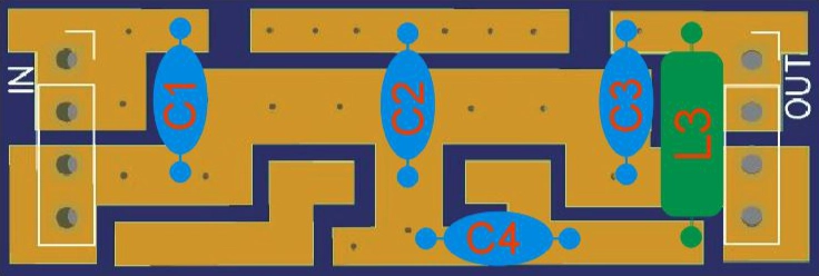 | 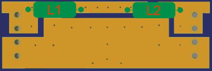 |
| 15M | 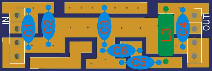 |  |
| 20M |  | 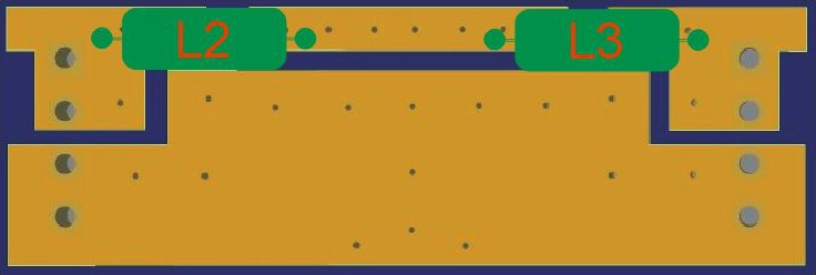 |
| 40M |  | 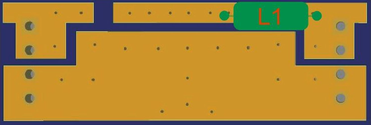 |
| 80M | 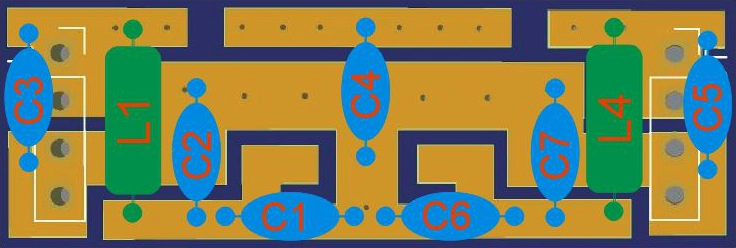 | 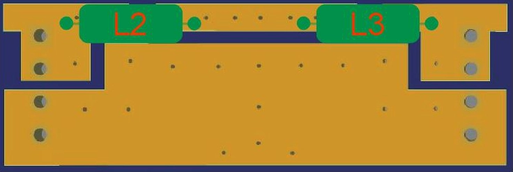 |
| 160M | 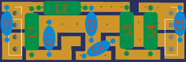 |  |
Component Identification Guide
For greater clarity of assembly, the usual identification of the different components that make up the filters is provided:
Component Identification Table
| AXIAL INDUCTORS | CAPACITORS | ||
|---|---|---|---|
| VALUE | COLOR BANDS | VALUE | SILKSCREEN |
| 0.33 μH | ORANGE - ORANGE - SILVER - SILVER | 1 pF | 1.0 or 1p0 |
| 0.47 μH | YELLOW - VIOLET - SILVER - SILVER | 1.2 pF | 1.2 or 1p2 |
| 0.68 μH | BLUE - GRAY - SILVER - SILVER | 5.6 pF | 5.6 or 5p6 |
| 1 μH | BROWN - BLACK - GOLD - SILVER | 12 pF | 12 |
| 1.5 μH | BROWN - GREEN - GOLD - SILVER | 15 pF | 15 |
| 2.2 μH | RED - RED - GOLD - SILVER | 18 pF | 18 |
| 4.7 μH | YELLOW - VIOLET - GOLD - SILVER | 22 pF | 22 |
| 5.6 μH | GREEN - BLUE - GOLD - SILVER | 27 pF | 27 |
| 8.2 μH | GRAY - RED - GOLD - SILVER | 39 pF | 39 |
| 100 pF | 101 or n10 | ||
| 120 pF | 121 or n12 | ||
| 220 pF | 221 or n22 | ||
| 270 pF | 271 or n27 | ||
| 470 pF | 471 or n47 | ||
| 680 pF | 681 or n68 | ||
| 820 pF | 821 or n82 | ||
| 1500 pF | 152 or 1n5 | ||
| 2200 pF | 222 or 2n2 | ||
Filter PCB Design and Construction
The proposed PCB, for which a Gerber file link is provided for downloading and ordering manufacturing (see the BOM table at the bottom), consists of 10 mini boards (which must be cut with a saw) for 10 possible filters. The design took into account that it should be a very versatile board and could contain 5 or 7-pole filters, even with some "notch" associated with a specific frequency. The chosen format is for "Manhattan" style construction (components soldered on "islands") due to the enormous flexibility of design and type of component that can be used.

Filter Installation and Connection
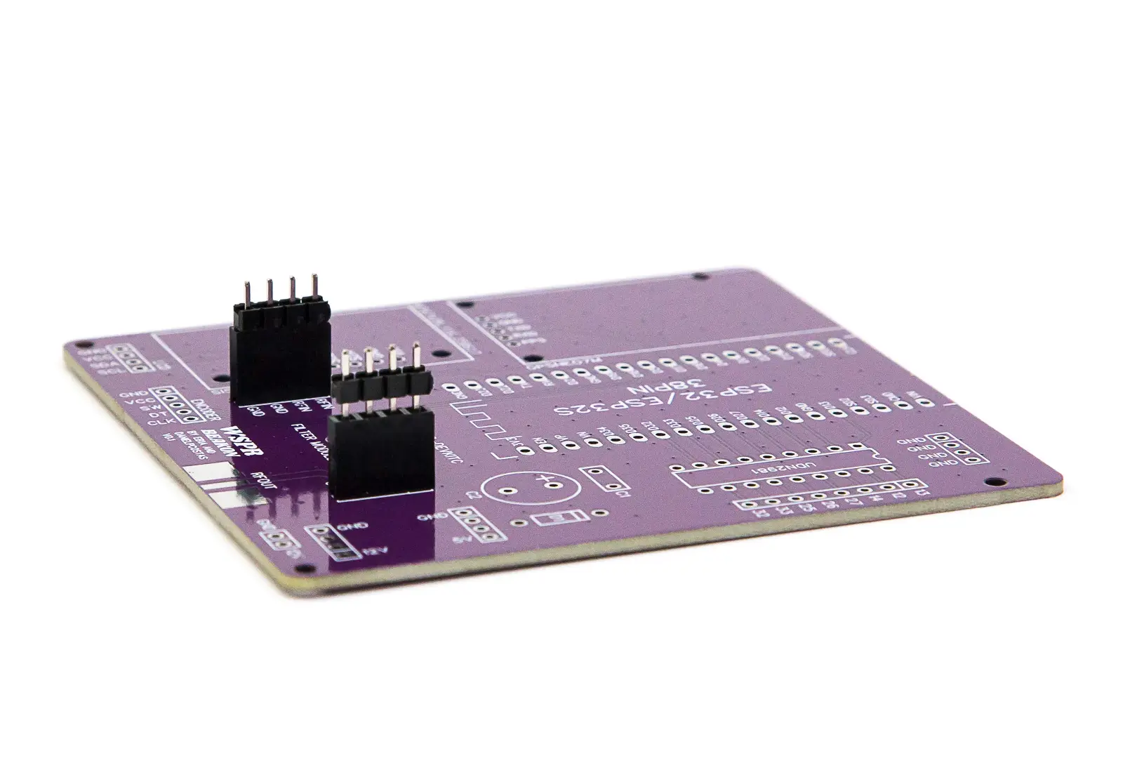
Filter boards are connected to the main assembly board via insertable pins, making them very easily interchangeable. A good way to ensure these pins are well aligned when soldering and that the boards can then be easily exchanged is to follow these steps:
-
Socket Installation: Solder the two 4-pin female sockets on the main board, pressing them against the board during soldering so they are properly seated and form 90 degrees with respect to the board
-
Pin Insertion: Insert the two 4-pin male strips, through their long side, onto the female sockets already soldered
-
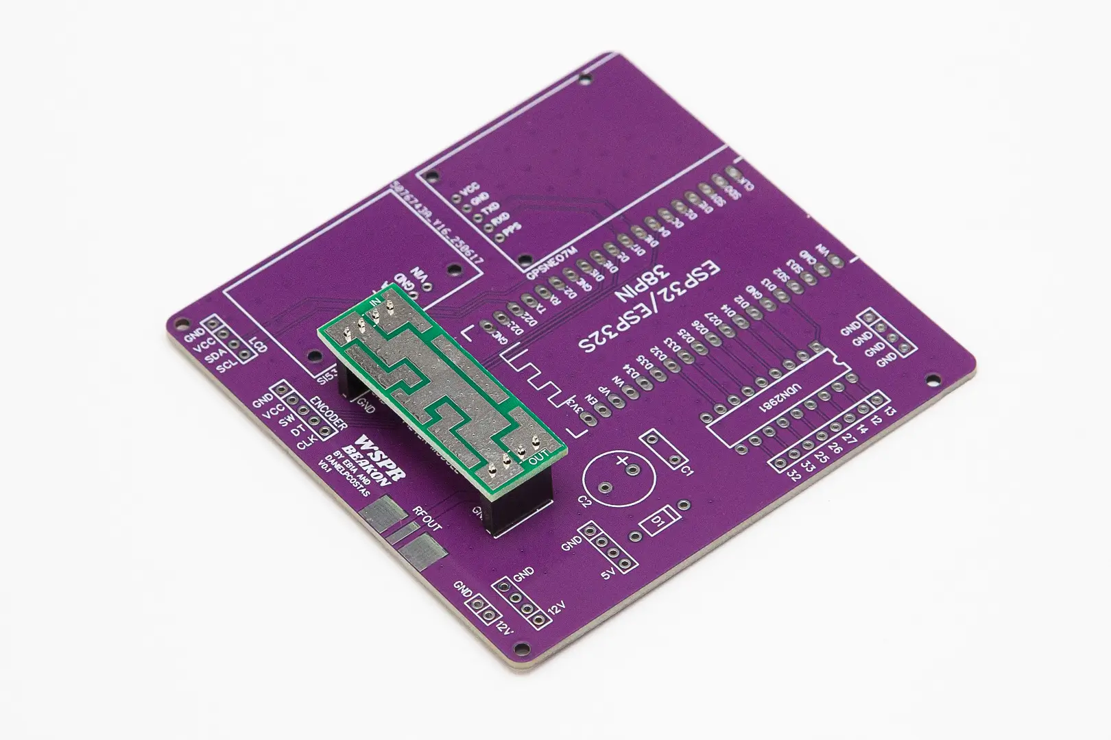
Filter Board Mounting: Place the filter board on the male pin strips (careful: check that the "IN" and "OUT" silkscreen of the filter board faces up and matches the "RFIN" and "RFOUT" silkscreen of the main board), ensuring it seats properly and proceed to solder the eight male pins to the filter board


Alternative SMA Connector Configuration
Although the filter boards were initially designed to be used in this project and connected via pin strips, the arrangement of the "ground" and "RF" tracks allows for soldering SMA connectors for 1.6mm circuit boards (which require cutting two of their four "ground" pins) and thus be able to use them in any other project that requires this type of connectors.

Filter Testing and Verification
Testing Setup Options
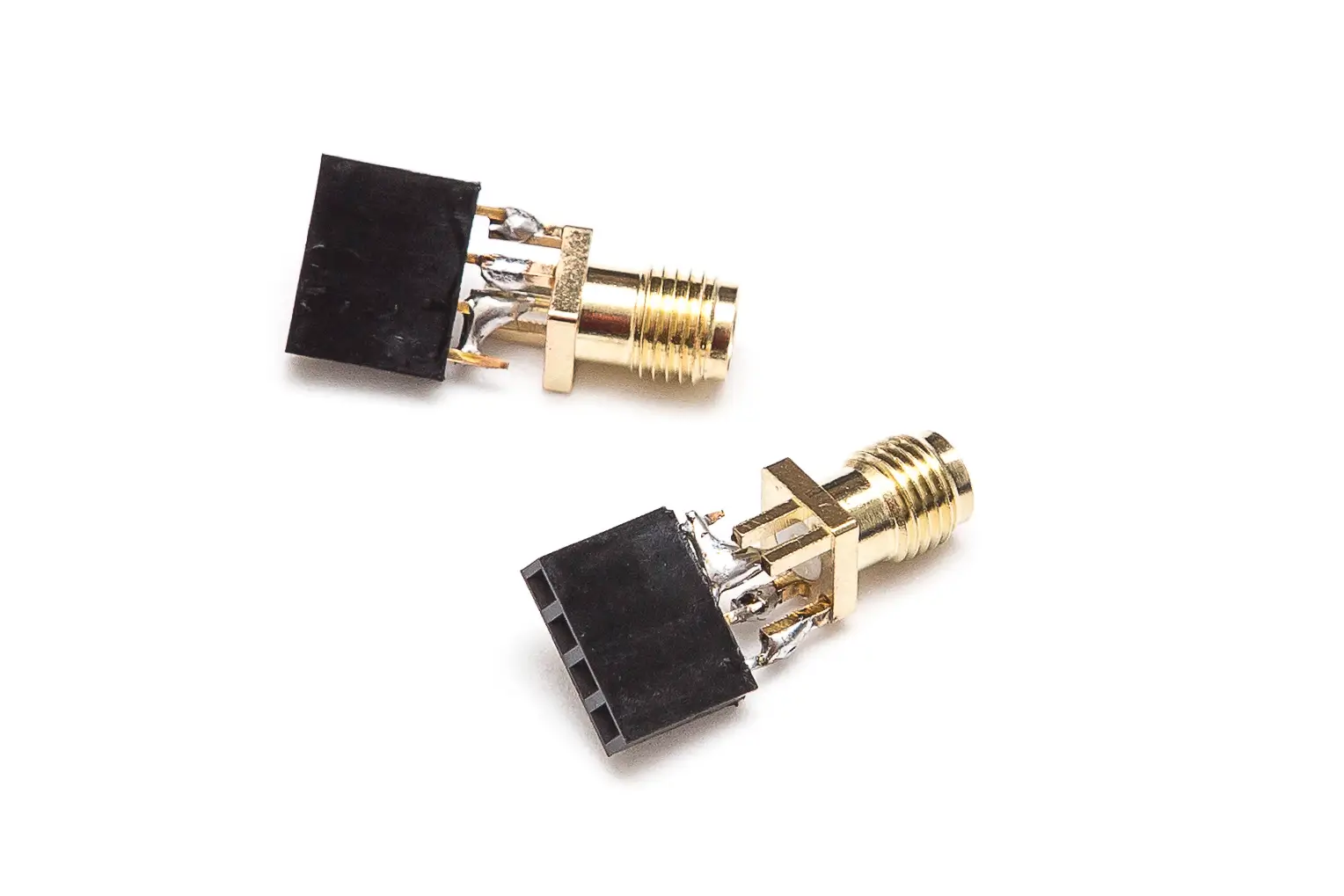
To proceed with filter adjustment and verification (MANDATORY), they must be connected to measuring equipment, such as a nanoVNA. For this we can prepare a pair of "transitions" from pin connector to SMA (taking care that the pins of the "live" of the SMA connector are then placed in those corresponding to the "IN" and "OUT" of the filter board):


Expected Filter Response
The graphs we will obtain in the measuring equipment, depending on the type of filter used, should be similar to the following examples:
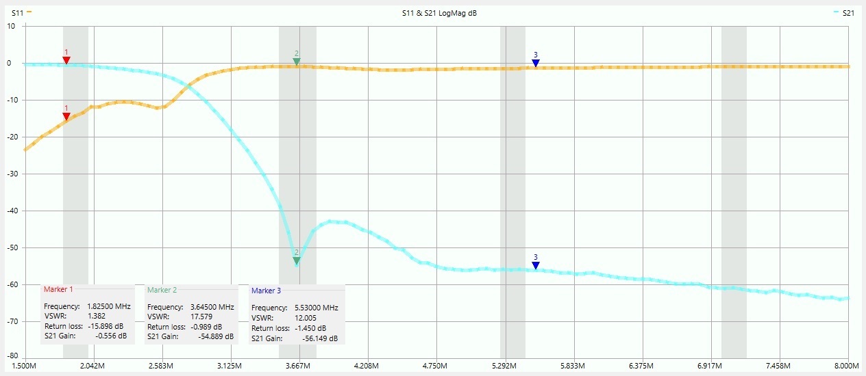
160 meter filter with a notch at the second harmonic (3.6 MHz) to improve its attenuation

15 meter filter with a notch at the second harmonic (42.3 MHz) to improve its attenuation
When exchanging filters on the main board to change bands, special attention must be paid to ensure that the "IN" silkscreen of the filter faces towards the RF module (and matches the "RF IN" silkscreen of the main board), and that we insert all 4 pins of both sockets. It may happen, if we do not pay attention, that one of the pins remains outside its socket, which would lead to totally anomalous behavior of the assembly.