Software Flashing & Config
This section covers the firmware installation and parameter configuration for your WSPR Beakon system.
The complete source code, libraries, and documentation for the WSPR Beakon project are available at:
https://github.com/danielcharrua/wspr-beakon
Make sure to download or clone the repository to access all necessary files before proceeding with the installation.
Software Installation
Prerequisites
- Arduino IDE: Download and install from arduino.cc
- ESP32 Package: Install ESP32 support in Arduino IDE
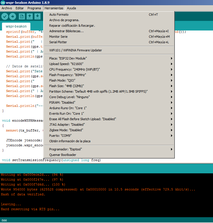
Arduino IDE Configuration
Configure Arduino IDE with the following settings:
- Board: ESP32 Dev Module
- Upload Speed: 921600
- CPU Frequency: 240MHz (WiFi/BT)
- Flash Frequency: 80MHz
- Flash Mode: QIO
- Flash Size: 4MB (32Mb)
- Partition Scheme: Default 4MB with spiffs
- Core Debug Level: None
- PSRAM: Disabled
- Programmer: Esptool
Library Installation
- Download all library ZIP files from the GitHub repository lib/ folder
- Copy the extracted folders to your Arduino libraries directory:
- Windows:
Documents\Arduino\libraries\ - macOS:
~/Documents/Arduino/libraries/ - Linux:
~/Arduino/libraries/
- Windows:
Required libraries:
- Etherkit Si5351 (v2.1.4)
- JTEncode (v1.2.0)
- LiquidCrystal I2C (v1.1.4)
- NTPClient (v3.1.0)
- RotaryEncoder (v1.5.2)
- Time (v1.5)
- TinyGPSPlus (v1.1.0)
Firmware Upload
If you are powering the circuit from an external source, it is STRONGLY RECOMMENDED that this source be turned off before connecting a PC to the ESP32 module. FAILURE TO DO SO MAY IRREPARABLY DAMAGE THE PC.
- Connect your ESP32 to your computer via USB cable
- Open
wspr-beakon.inoin Arduino IDE - Configure the required parameters (see Configuration section below)
- Select the correct COM port in Arduino IDE
- Click "Upload" to flash the firmware
Software Configuration
Before uploading the firmware, you must modify the configuration variables in the USER CONFIGURATION section of the code according to your chosen configuration:
Development Mode Configuration
#define DEVMODE // Serial port debug
- Development: Keep
#define DEVMODEuncommented for debugging and troubleshooting - Production: Comment out this line (
// #define DEVMODE) for optimal performance in final deployment
Basic WSPR Configuration
// WSPR transmitter configuration
#define WSPR_CALL "EA1REX"  // Your 4-6 character callsign
#define WSPR_LOC "IN53"     // Your 4-character grid locator
#define WSPR_DBM 10         // Power level shown in WSPR frame (0, 3, 7, 10 dBm)
#define WSPR_TX_EVERY 4     // Transmit every X minutes (2, 4, 6, 8, 10, etc.)
Si5351 Power Level
// Available options: SI5351_DRIVE_2MA, SI5351_DRIVE_4MA, SI5351_DRIVE_6MA, SI5351_DRIVE_8MA
// Power output (tested values): SI5351_DRIVE_2MA = 1mW, SI5351_DRIVE_4MA = 2mW, SI5351_DRIVE_6MA = 5mW, SI5351_DRIVE_8MA = 10mW
#define SI5351_DRIVE_LEVEL SI5351_DRIVE_4MA
WiFi Networks Configuration
For base configuration (NTP synchronization):
const WiFiNetwork wifiNetworks[] = {
  {"Your_SSID_1", "password1"},
  {"Your_SSID_2", "password2"},
  {"Your_SSID_3", "password3"}
};
"Your_SSID_1" is the name of your WiFi network
Band Configuration
Configure frequencies, crystal calibration, and relay pins for each band:
} wsprFrequencies[] = {
  // Frequency(Hz), Crystal_Freq(Hz), Label, Relay_Pin
  {144489000UL, 25000000UL, "144.489 MHz 2m",  0},    // 2m band (not supported by the Si5351)
  {70091000UL,  25000000UL, "70.091 MHz 4m",   0},    // 4m band (not supported by the Si5351)
  {50293000UL,  25000000UL, "50.293 MHz 6m",   0},    // 6m band (not supported by the Si5351)
  {40680000UL,  25000000UL, "40.680 MHz 8m",   0},    // 8m band
  {28124600UL,  25000000UL, "28.124 MHz 10m",  12},   // 10m band
  {24924600UL,  25000000UL, "24.924 MHz 12m",  12},   // 12m band
  {21094600UL,  25000000UL, "21.094 MHz 15m",  14},   // 15m band
  {18104600UL,  25000000UL, "18.104 MHz 17m",  14},   // 17m band
  {14095600UL,  25000000UL, "14.095 MHz 20m",  27},   // 20m band
  {10138700UL,  25000000UL, "10.138 MHz 30m",  27},   // 30m band
  {7038600UL,   25000000UL, "7.038 MHz 40m",   26},   // 40m band
  {5364700UL,   25000000UL, "5.364 MHz 60m",   26},   // 60m band
  {3568600UL,   25000000UL, "3.568 MHz 80m",   25},   // 80m band
  {1836600UL,   25000000UL, "1.836 MHz 160m",  33},   // 160m band
  {474200UL,    25000000UL, "0.474 MHz 630m",  32},   // 630m band
  {136000UL,    25000000UL, "0.136 MHz 2200m", 32}    // 2200m band
};
Relay Pin Assignment
The following ESP32 pins are used for band relay control:
- Pin 12: 10m, 12m bands
- Pin 14: 15m, 17m bands
- Pin 25: 80m band
- Pin 26: 40m, 60m bands
- Pin 27: 20m, 30m bands
- Pin 32: 630m, 2200m bands
- Pin 33: 160m band
- Initial Crystal Frequency: For the first upload, set all crystal frequencies to
25000000UL(25 MHz) - Calibration Required: After initial upload, you'll need to calibrate each band for frequency accuracy
- Custom Frequencies: The provided frequencies are examples - you must calculate your own based on your specific Si5351 crystal
Very Important: Once new code is uploaded to the ESP32, it is necessary to make a band selection using the encoder (see next section) for the microcontroller to initialize correctly. Otherwise, the assembly operation will be erratic.
Rotating Band Transmission Functionality
The code can be configured so that the equipment transmits alternately on different bands in a rotating manner; this can be useful for someone using a multiband antenna. With this option enabled, the transmission sequence would be as follows: I transmit on band “A”; I rest for “X” minutes; I transmit on band “B”; I rest for “X” minutes; I transmit on band “C”; I rest for “X” minutes; then the cycle starts again by transmitting once more on band “A”.
Before enabling this functionality, the following premises must be taken into account:
A filter switching system that covers the bands to be used must be enabled
- An antenna matched to the bands to be used must be employed
- The minimum time between transmissions will be 4 minutes (this implies two minutes of rest between transmissions)
- As many rotating bands as desired can be assigned
- The rotary encoder will no longer be used to select the operating band, since the bands will alternate according to the selection made in the code. In any case, once the new code is uploaded, a band selection must be made with the encoder in order to correctly initialize the device
To enable this functionality, the following line of code must be changed:
#define WSPR_AUTO_ROTATION false // Set to true to auto rotate frequencies after each transmission
Change the WSPR_AUTO_ROTATION parameter from false to true, and then add, at the beginning of the lines of code corresponding to the different bands, a pair of forward slashes // on each of the bands that we do not want to be part of the rotating transmission. For example, in this block of code lines, only the 10, 15, and 20 meter bands have been left enabled (a typical case for someone who wants to use this functionality with a standard triband antenna):
} wsprFrequencies[] = {
  // Frecuencia(Hz), Freq_Cristal(Hz), Etiqueta, Pin_Relé
  //{144489000UL, 25000000UL, "144.489 MHz 2m",  0},    // 2m band (not supported by the Si5351)
  //{70091000UL,  25000000UL, "70.091 MHz 4m",   0},    // 4m band (not supported by the Si5351)
  //{50293000UL,  25000000UL, "50.293 MHz 6m",   0},    // 6m band (not supported by the Si5351)
  //{40680000UL,  25000000UL, "40.680 MHz 8m",   0},    // 8m band
  {28124600UL,  25000000UL, "28.124 MHz 10m",  12},     // 10m band
  //{24924600UL,  25000000UL, "24.924 MHz 12m",  12},   // 12m band
  {21094600UL,  25000000UL, "21.094 MHz 15m",  14},     // 15m band
  //{18104600UL,  25000000UL, "18.104 MHz 17m",  14},   // 17m band
  {14095600UL,  25000000UL, "14.095 MHz 20m",  27},     // 20m band
  //{10138700UL,  25000000UL, "10.138 MHz 30m",  27},   // 30m band
  //{7038600UL,   25000000UL, "7.038 MHz 40m",   26},   // 40m band
  //{5364700UL,   25000000UL, "5.364 MHz 60m",   26},   // 60m band
  //{3568600UL,   25000000UL, "3.568 MHz 80m",   25},   // 80m band
  //{1836600UL,   25000000UL, "1.836 MHz 160m",  33},   // 160m band
  //{474200UL,    25000000UL, "0.474 MHz 630m",  32},   // 630m band
  //{136000UL,    25000000UL, "0.136 MHz 2200m", 32}    // 2200m band
};