Frequency Calibration for Each Band
This section covers the frequency calibration process required for each band of your WSPR Beakon system.
Why Calibration is Required
Once the initial code is loaded into the assembly, each band of interest must be calibrated individually (this process is not necessary for bands you won't use). There are variations between bands and also variations between different Si5351 modules. If you need to replace a Si5351 module due to failure, the calibration process must be repeated.
The initial code sets the crystal frequency for each band to 25000000 Hz. This frequency must be adjusted to correctly center the transmission in the WSPR segment, which is quite narrow. This step is mandatory and must be performed rigorously, as placing your transmission outside the assigned segment will prevent anyone from reporting your frames.
Proper frequency calibration is essential for WSPR operation. Signals outside the designated WSPR segment will not be decoded by other stations.
Required Equipment
For calibration, you'll need:
- A transceiver (or receiver) that is reasonably frequency-accurate with PC connection. Any modern equipment used for digital modes should suffice
- WSJT-X software (downloadable from the official website)
- Access to the online calibration calculator
Calibration Procedure
Initial Setup
-
Configure transmission interval: Set the assembly to transmit every 4 minutes (optional, but reduces waiting time between transmissions)
-
Install appropriate filter: Install the filter for the band you want to calibrate
-
Connect dummy load: Install a dummy load on the RF output connector (or an antenna as a better alternative)
-
Power up the assembly: Apply power to start the system
-
Select target band: Use the encoder to select the band of interest (same as the installed filter). Note: Band changes are not possible during TX or warm-up periods
Stabilization Period
- Wait for stabilization: Allow 10 minutes for the Si5351 module to stabilize in temperature and frequency
The Si5351 is very sensitive to slight air currents that cause temperature changes and frequency drift. If the assembly is exposed, cover it (even with a cardboard box) to prevent frequency instability. Unstable frequency causes WSPR frames to appear visibly "tilted" on waterfall displays and prevents proper decoding.
Receiver Setup
-
Configure reference transceiver:
- Turn on the transceiver to be used as reference
- Tune to the WSPR frequency for the band being calibrated (always USB mode, regardless of band)
- Classic band frequencies (160-10m): 1.836600, 3.568600, 7.038600, 14.095600, 21.094600, and 28.124600 MHz
- Complete frequency list available at: WSPR Frequencies
-
Coupling setup: Connect the transceiver to:
- A dummy load placed near the assembly, or
- A short cable with open connector placed near (but not touching) the assembly
- Goal: Receive the assembly's transmission without external interference
If using antennas for both transceiver and assembly (best option for signal identification), activate attenuator and/or reduce RF gain to prevent RF overload problems.
WSJT-X Configuration
-
Launch WSJT-X:
- Select WSPR mode
- Select the band being calibrated
- If CAT control is configured, the program will automatically set the correct frequency
-
Open waterfall display:
- Select "View" menu → "Wide Graph (Waterfall)"
- WSPR signals must appear between 1400 and 1600 Hz (only 200 Hz window)
Signal Analysis
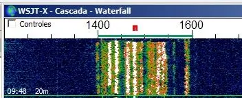
WSPR signals within the correct passband, between 1400 and 1600 Hz
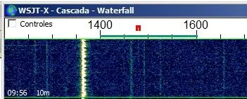
WSPR signal outside the correct passband. This signal will never be decoded
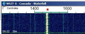
WSPR signal within the correct passband
Frequency Measurement and Correction
-
Check signal position:
- If signal is within 1400-1600 Hz (preferably not near edges): Calibration complete for this band
- If signal is outside the window: Continue with correction process
-
Locate your signal:
- Use transceiver dial to move up or down until you find your signal
- Position it within the correct spectrum portion (avoid extremes due to potential frequency variations)
-
Record actual frequency: Note the frequency (in Hz) where you had to tune the transceiver to correctly receive your signal
Calculate New Crystal Frequency
-
Use online calculator: Access the calibration calculator at:
-
Enter parameters:
- Desired frequency: Official WSPR frequency for the band (in Hz, without commas or decimal separators)
- Obtained frequency: Frequency you tuned on the transceiver to center your signal (in Hz)
- Initial crystal frequency: 25000000 (default value loaded in ESP32 code)
-
Calculate result: Click "Calculate" to get the new crystal frequency (e.g., "Adjusted Crystal Frequency: 25008771 Hz")
If the result includes decimals (e.g., 25008771.24 Hz), ignore the decimal portion and use only the whole number.
Completing Calibration
Repeat for All Bands
- Repeat process: Perform this calibration procedure for all bands of interest
Update Code
-
Modify crystal frequencies:
- Return to the code upload page
- Replace the default 25000000 value with the calculated value for each calibrated band
- Leave uncalibrated bands (not to be used) with the default value
-
Adjust transmission interval: Modify transmission periods from 4 minutes to a more typical interval (8-10 minutes; always even numbers)
-
Upload new code: Load the updated code to the ESP32
Final Initialization
- Critical post-upload step: After uploading new code, you must select a band using the encoder (see previous section) for proper microcontroller initialization. Otherwise, the assembly will operate erratically.
Verification
After completing all calibrations:
- Your assembly should be properly calibrated for all bands of interest
- The system is ready for normal WSPR operation
- Verify each band produces signals within the correct WSPR passband