Project Overview
Welcome to the comprehensive documentation for the WSPR Beakon - a modular and expandable WSPR (Weak Signal Propagation Reporter) beacon transmitter based on ESP32 microcontroller with Si5351 clock generator.
What is WSPR?
WSPR (Weak Signal Propagation Reporter) is a digital protocol and computer program used for weak-signal radio communication between amateur radio operators. The protocol was developed by Nobel Prize-winning physicist Joe Taylor (K1JT).
WSPR is a radio mode whose primary use is the study of propagation across different amateur radio bands, and it also effectively enables direct comparison of different antennas or locations. It uses two-minute transmission periods and typically employs very low power, with the most common range being between one milliwatt (1 mW) and one watt (1 W). In very general terms, it could be said that a 1-watt transmission in WSPR is equivalent to 10 watts in FT8, 100 watts in CW, or 1000 watts in SSB.
There is a large network of WSPR receiving stations distributed worldwide across different bands, and many of these stations upload their reports to the WSPR website: https://www.wsprnet.org/drupal/wsprnet/map. This website initially presents a map of reports where you can filter by band, callsign, time period, etc. The same website, in the "Database" section, allows you to obtain a detailed text listing with comprehensive information on which search filters can also be applied.
For more information about WSPR, you can visit: https://en.wikipedia.org/wiki/WSPR_(amateur_radio_software)
About the WSPR Beakon
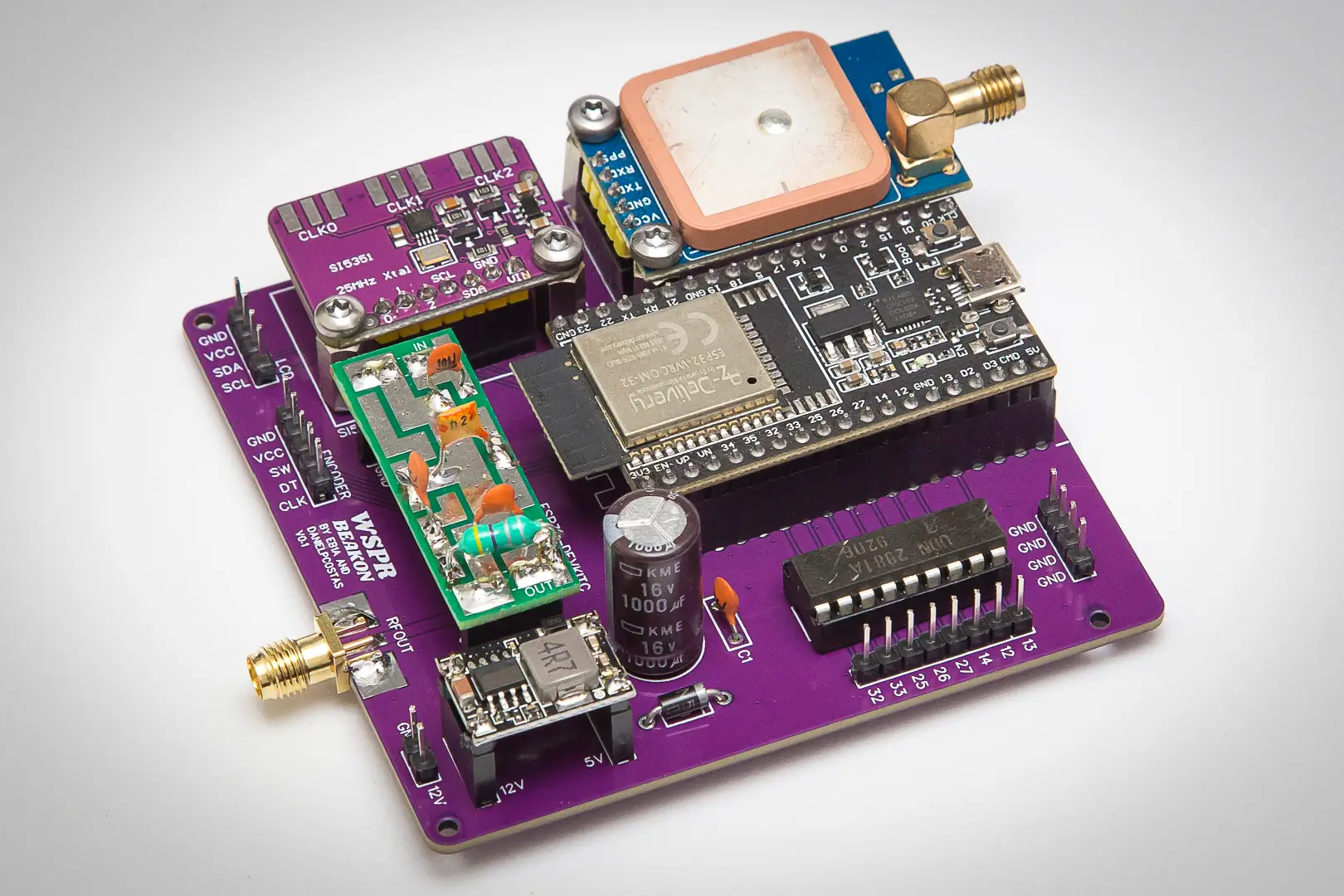
The proposed assembly is designed to transmit on HF, MF, and LF bands. The WSPR Beakon is designed with a modular approach that allows implementing different configurations according to user needs, from a basic version to a fully equipped system.
Key Features
- Multiband operation: From 2200m to 2m (hardware limited to 10m)
- Modular design: Expandable system with optional enhancements
- Time synchronization via WiFi: Essential requirement for WSPR transmission mode, with support for multiple simultaneous network configurations
- Time synchronization via GPS module: Includes integrated antenna with option to connect external antenna
- LCD display: Shows various equipment parameters and status information
- Rotary encoder: For selecting the operating band
- Built-in filter sockets: PCB-mounted sockets for low-pass filter insertion
- Configurable output power: Four-step power control between 1 and 10 milliwatts
- Seven relay outputs: High-level outputs configurable according to operating band
- TX/RX relay output: High-level output that activates/deactivates with transmission changes
- Warm-up transmission period: Pre-transmission period to stabilize RF module frequency drift, especially important at higher frequencies
- Transmission blocking: Prevents transmission if valid time synchronization cannot be achieved via WiFi or GPS
While the software supports frequencies up to 2m (144 MHz), the current hardware implementation using the Si5351 clock generator module is practically limited to frequencies up to 10m (28 MHz) due to the module's frequency response characteristics.
Before You Begin
To use this assembly in practice by connecting it to a real antenna, you MUST have a valid amateur radio license or administrative authorization that enables you to do so, i.e., have an officially assigned amateur radio callsign.
THE USE OF A FILTER AT THE TRANSMITTER OUTPUT IS ABSOLUTELY IMPERATIVE. The RF module generates multiple harmonics that must be eliminated before putting a signal on the air. The circuit board includes sockets for inserting a low-pass filter, which generally operates in a single-band mode, so experimentation on multiple bands usually requires substituting one filter for another. THE MANDATORY USE OF RF FILTERING ELEMENTS IS REITERATED.
If you are powering the circuit from an external source, it is STRONGLY RECOMMENDED that this source be turned off before connecting a PC to the ESP32 module. FAILURE TO DO SO MAY IRREPARABLY DAMAGE THE PC.
WSPR is a highly effective mode designed for the use of very moderate power levels, generally below 1 watt, with the use of a few milliwatts being very common. Let's keep this in mind when making responsible use of the spectrum.
Important Assembly Considerations
This assembly, although it may appear otherwise from the initial photograph, involves more than just assembling the different modules that comprise it. Even in the most basic version, filters must be assembled (by soldering components) and you need knowledge to adjust them with measuring equipment (for example, a nanoVNA), and the output frequency must also be calibrated with appropriate measuring equipment or with a receiver (or transceiver) reasonably adjusted in frequency. In essence, this is not a plug-and-play project.
A complete reading of this documentation is recommended before beginning the proposed assembly, as there are some elements that are soldered or not depending on the chosen operating option, and it could happen that something unnecessary for our intentions has been soldered or acquired. A complete and careful reading will give us a general overview to choose the assembly option that best fits our expectations.
The documentation is quite extensive in order to provide exhaustive descriptions and clear up all possible doubts that might arise. The most complex part of the assembly is the filters, but nothing that cannot be tackled with a little patience and focusing on the bands of interest, so it is probably not necessary to make all six proposed filters.